This article came from ArtiFax Books in 2001.
Found at the Internet Archive.
Enjoy
Using vintage telegraph instruments:
Applying power to old sounders.
Applying power to old sounders.
Collecting old landline telegraph keys, sounders and relays is an interesting hobby. These historic communication instruments were "state of the art" back in the 1800s, and were still in use right up through the 1950s and later. They bring visions of the American West and railroads. They make interesting display pieces.
More interesting is to hook them up to a battery and try them out. Re-create the sound of the Western Union office and the old railroad depot. On this page I will try to help you check out and power up your sounders. References to back issues of The Vail Correspondent (TVC) are given for those who want to research this field in more detail.
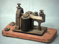
The typical sounder is simply two electromagnets (coils of wire on an iron core) set up to attract a steel
bar. This bar is attached to a non-magnetic (brass or aluminum) lever. When the magnets are activated the lever is pulled down, producing a "click" when the lever is stopped by an adjustable screw. When the circuit is broken, a spring returns the lever to its original position, causing a "clack" as the lever hits another stop screw.These sounds, and the time interval between them, are used to send a message in Morse Code. (Reference: TVC8.)
A sounder should be adjusted so that a small gap (the thickness of a sheet of paper is enough) is left between the bar and the magnets when the sounder is energized. Then adjust the upper lever stop screw so there is about 1/16 inch of lever travel. Finally, adjust the spring so that the lever moves easily. (The last two adjustments can be refined later to produce the most pleasing sound.)
Before you can get a sounder to work there must be electrical continuity in the wiring, from one wire terminal to the other. A quick test with a 3 to 6 volt battery may do -- but just touch the battery wires to the terminals quickly, since this may be too much voltage for some sounders. On the other hand, it may not be enough voltage for other sounders; if the lever does not pull in, press it down and see if it's held by the magnets. If so, the circuit is complete.
Or you can test the wiring with an ohmmeter. This will also tell you (if the wiring is good) the resistance of the sounder, which you will need to know. If the battery or meter test is not successful, it may be simply that the corrosion on the wires and terminals will not permit the proper result. In that case, clean the surfaces. Broken wires are common, and will have to be repaired.
Now determine the sounder resistance. This is usually stamped on
the top or side of the instrument. If not, use your ohmmeter. Sounders
are current-operated instruments. Generally the following applies (these
are not critical; a 25% variation would not be harmful to the
instrument):
... 4-ohm instruments are intended for 250 milliampere lines, and require 1 volt;
... 20 ohm instruments require 175 ma (3.5 volts); and
... 150 ohm main line instruments require 40 ma (6 volts).
In the old days, gravity batteries ("crowfoot battery") might be used. One gravity cell puts out about 1.08 volts. A 4-ohm sounder in my collection has a Western Union label on it that says "This sounder is designed for use with one cell only of gravity battery." (Batteries are discussed in TVC17). For home use, common dry cells are sufficient. You might, for example, use one or two D cells (1.5 to 3 volts) for a 4-ohm sounder. Putting a milliammeter in the circuit will be helpful. Of course, a vintage Western Union meter is best!
You may find your sounder to be "sluggish" even though you have applied the proper voltage; this is more often the case with high-resistance (main line) instruments -- 100 to 150 ohms. You may be tempted to increase the voltage to get a good sound out of it. But this is the wrong approach. The sluggishness of operation is due to the inductance of the magnet coils and the relatively long time constant of the circuit. The time constant is proportional to the inductance, and inversely proportional to the resistance of the circuit: T=L/R.
To get "snappy" sounder operation, you should decrease the time constant. Looking at the formula, this is done by increasing the resistance of the circuit (adding a series resistor, or so-called "ballast"). Now, in order to get the required current again, you may increase the voltage (see TVC10). Use non-inductive resistors, of course.
I hope this information will help you get more enjoyment out of your collecting. More information on Morse instruments appears in the "Landline" column of TVC. (Note, TVC is no longer published, although back issues are available. See the TVC page on this web site.) Landline telegraph instruments, circuits and practices are also included in the "Railroad Telegrapher's Handbook" and in Prescott's "History, Theory and Practice of the Electric Telegraph".


No comments:
Post a Comment